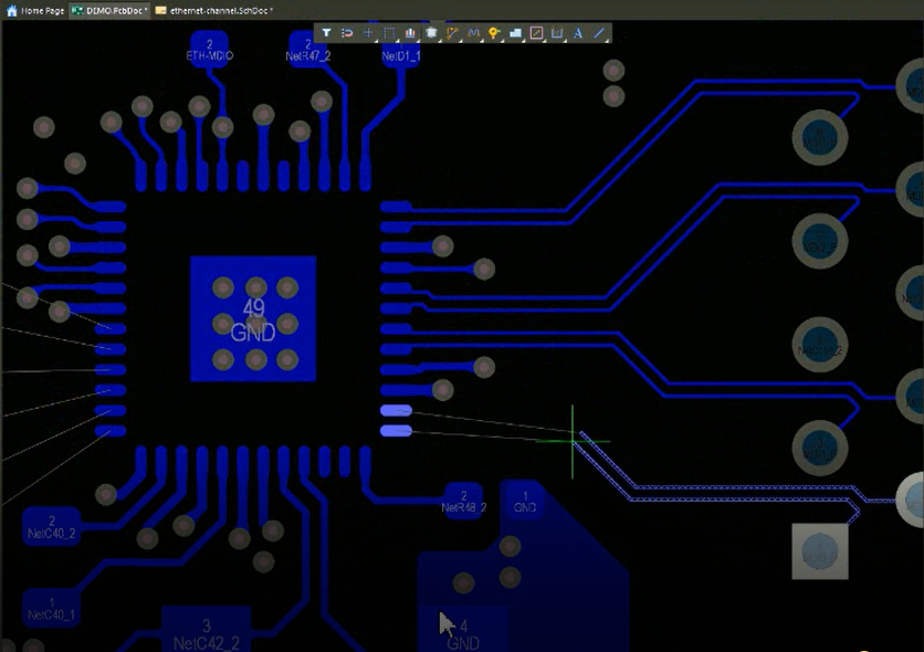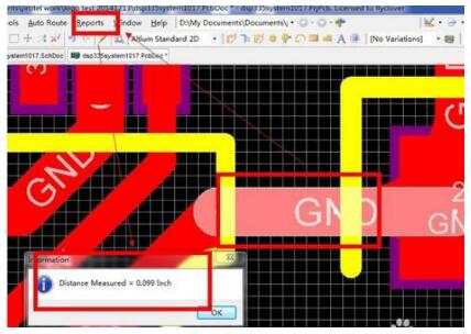

The capture of the round net tie component above has a clearance violation using a standard clearance rule of 0.254 mm.

Round net tie constructed of two semi-circle polygonsĭepending on the size and layout of the net tie component footprint, some PCB rules may require adjustment.įor the rectangular net tie component shown above, the distance between the individual traces is greater than 0.254 mm. PCB Net Tie with Rectangular Solder Masked Pads PCB Net Tie with Rectangular Exposed Pads The capture below illustrates a surface mount net tie with exposed pads. Some designs may opt for a component such as a resistor with connected pads or thru-hole pad.Īltium Net Naming with a Net Tie, No Power Port PriorityĪ close-up of the net tie for the example is pictured below with side-by-side surface mount pads. To retain the two separate net names, 0 V and ADC_Sig.IN0_N, a component is required to separate the nets.Įxample ADC Connections for Current Sensing with Net Tieįor separating the nets, a net tie component is commonly used. The net on the PCB appears as 0 V as shown in the capture below.Īltium Net Naming without a Net Tie, Power Port Priority Note that the 0 V net was renamed to ADC_Sig.IN0_N.Īctivating the power port priority checkbox in the Altium Netlist Options will ensure that the ADC_Sig.IN0_N net is renamed to 0 V. Net naming is shown in the capture below.Īltium Net Naming without a Net Tie, No Power Port Priority Using the example schematic with Altium defaults shown below, parts were placed on a Printed Circuit Board (PCB). Incorrect board routing can result in issues such as excessive noise floor voltages or inaccurate measurements not representative of the source (R1).Įxample ADC Connections for Current Sensing without Net Ties During routing of the board traces, the pin at the ADC input may be inadvertently tied to 0 V. The risk in connecting the negative ADC input, IN0_N, to the 0 V is the net name given to the pin. For the purposes of this blog, the differential voltage measurement has negative connection of the ADC referenced to 0 V. In the example circuit below, a differential voltage measurement is required for an Analogue to Digital (ADC) device. Initially, the requirement to use a net tie may not be apparent. Developers support pages should be a readers the first destination when knowing that a net tie is required for a design.

The Altium website contains examples for using net tie components, such as those listed on the page " Breaking the PCB Design Challenges with Net Ties". Although Altium Designer was used to illustrate the net tie example, many existing packages support net tie functionality. This blog presents an example design employing a net tie component.


 0 kommentar(er)
